Testing, learning, improving: SCAPE converter validation moves towards motor and battery environments
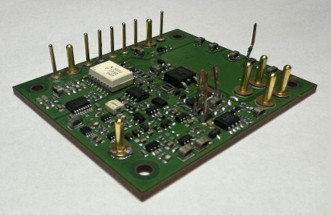
The purpose of validation is not simply to produce a final “pass” result. In a research prototype, the most valuable tests are often those that reveal interactions that were not fully visible in simulation or at lower power. SCAPE has now entered that phase with the chip-embedded converter legs and is using the findings to strengthen the system before final validation.
The test bench has been progressively commissioned with improved safety measures and a dedicated arming state machine. Tests begin with auxiliary supplies and command signals, move to DC-link operation without switching, and then add switching and load while monitoring the voltages and temperatures inside the switching cells.
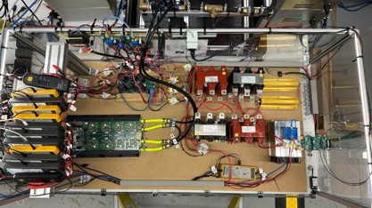
By the June 2026 General Assembly, the converter leg under test had completed short no-load tests up to 660 V and resistive-load tests up to 600 V / 3 A peak. It also reached combined converter-leg testing at 600 V / 40 A peak. That higher-current test revealed an abnormal state transition in the FPGA control, after which switching-cell components were found damaged. Rather than treating this as a final failure, the team used it to define the next engineering actions.
Other commissioning issues had already produced concrete design changes. When the switching pattern held a cell continuously on, the auxiliary regulator could enter undervoltage lockout; the control strategy was modified so that duty cycle never reaches one. A separate auxiliary-voltage peak was observed during the first switching events because the DC-link voltage was not initially distributed equally across the cells. A TVS diode was selected to clamp the transient and protect the DC-DC regulator. The team also identified a false over-current detection condition and adjusted the protection logic during the test campaign.
Following the high-current event, additional measures are being prepared to improve control robustness and electromagnetic compatibility. These include a more robust FPGA state machine, reductions in electromagnetic emissions on power cables, improved grounding and cable routing, and shielding around the FPGA electronics.
The next target is to resume converter-leg tests and progressively reach 800 V and 80 A RMS, first in short bursts and then for continuous operation with liquid cooling. During these tests the team will monitor MOSFET voltage overshoot, switching-cell temperatures, auxiliary heatsink temperature, inductor temperature and coolant temperature in order to define a practical safe operating area.
WP7 is also preparing the validation environments for the complete converter. In a controlled AVL-DE facility, the IIC will be tested for traction and grid charging using battery and motor emulators. A subsequent setup will introduce the real six-phase synchronous motor built for SCAPE, enabling traction, charging through the motor coils, regenerative braking and driving-cycle tests. A separate battery test bench will address battery impedance measurement, diagnostics and prognostics.
Alongside the technical validation, WP7 has consolidated a bottom-up cost-evaluation model based on the bill of materials, scaling from switching cells and converter legs to vehicle-level quantities and accounting for economies of scale. These results will feed the roadmap to market together with validation evidence, technology evolution, market trends and competitor analysis. The common objective is to connect the final laboratory results with realistic post-project R&D and industrialisation pathways.